Houdini Tip of the Day - Emit RBD Objects

It's been a while since the last time I posted anything but I thought this time I'd show how to emit RBD objects. A particularly useful setup that I've used numerous times to simulate rocks piling up.

In a nutshell all we are going to be doing is taking a piece of geometry that we want to use as out emitter geo, copy stamping random geo to each of it's points, transferring Velocity from a particle network, then converting the geo to RBD's that will fall and collide with whatever we have set up.

When I was originally learning this I was worried it was going to be complicated but I was relieved when I saw how simple the node graph was.

Lets dive in!

To start off, you will need some geometry that you want to emit from.
I've chosen to go with a box and then I animated a "Mountain" SOP to make all the points on the box move around in a crazy manner so when the objects get emitted from this object they will appear somewhat random.

After the Mountain SOP I added a "Point" SOP with "Add Normal" chosen under the "Standard" tab. I didn't end up using the normals in the end but it's always nice to have just in case. 

Now we need to generate some particles that we will use to copy some geometry onto. To do that, drop down a "Pop Network - Old" SOP and dive inside. 

In order be able to birth particles onto our emitter geo we need to use the "Source" POP. Set it to "Points(random)" and for Geometry Source choose "First Context Geometry". This will take whatever we have plugged into the first input of our particle network, just as Second, Third, and Fourth Context Geometry will respectively represent the other inputs on the particle network.
Change the "Const. Birth Rate" parameter to increase how many particles will be born. You don't have to worry about the "Life Expectancy" parameter just yet because we will be adding a "Kill" POP at the end to essentially make the Life Expectancy 0.

If you play the scene now, all you would see is a bunch of particles being generated on your emitter geo. Right now they aren't going anywhere though. Let's change that. Drop down a "Force" POP and change the Y Force to -9.8 (gravity). Now for this setup we might not even need the "Force" POP because we are going to be letting the gravity in DOP's affect how our objects fall, but I still like to put the "Force" POP in there just in case there comes a situation where I might need to emit particles for some amount of time before having DOP's take over.

The particles are now falling because of the "Force" POP

The last thing we want to do in our particle network is set the Life Expectancy to 0. We want the particles to emit, then die because as soon as they are emitted our DOP network will take over. Normally, you would just set the "Life Expectancy" parameter to 0 on the "Source" POP but you can also throw down a "Kill" POP and set the "Rule" to "@LIFE==0". This changes the LIFE attribute to 0.

Now lets jump back up to object level and start copying geo onto our particles.
For this example, I chose to keep it simple and just use three objects: a sphere, a box, and a tube.
Then I threw down a "Switch" node that we will use later to, well, switch randomly between our objects.

Okay now for the meat and potatoes of this setup. After the Switch node, drop down a "Copy" SOP and connect the Switch to the first input and the Particle Network to the second input. Then add a "Null" node at the end just to finish it off. (We'll be referencing back to this Null node when we go into DOP's)

Let's take a look at this Copy node.
For starters, on the "Copy" tab I checked on "Create Output Groups". We need this to be on for our setup in DOP's to see our objects. You can leave the "Copy Groups" parameter to it's default if you want but I changed mine to "piece_`$CY`_`$PT`". Essentially it's just there to add a different name to each piece when we bring it into DOP's so even "piece_`$PT`" will do just fine.

On the "Stamp" tab is really where everything is taking place.
We need to enable "Stamp Inputs". For the most part, the only things we want to randomize are the object, the object size, and the object's rotation. Here's how I've got my copy node setup:

If you know your basic fit01 expression then most of this is pretty self explanatory, but the expression I have for the "objSwitch" is a little different:

int(round(fit01(rand(@ptnum + $FF * 1000), 0, 3)))

All this expression is doing is taking a random number between 0 and 3 (3 being the number of different objects I have), then rounding it to the nearest whole number.
The only other thing left to do is transfer over any Velocity from our Particle Network. Again, we won't have any in this case becuase we are killing the particles as soon as they are born but if you have a different setup and need to transfer the Velocity you can actually do it inside the Copy SOP on the "Attribute" tab. All you need to do is type in "v":

Now that we have our Copy node up and working, we need to actually apply this to our scene because currently it's not doing anything.
In order to make use of the variables we made in the Copy SOP we need to apply them to our objects using the "stamp" expression:

stamp("../copy1", "objSwitch", 0)

So in this case we would use this expression on our Switch node because we know that the "objSwitch" variable that we made on our Copy node will return a random value between 0 and 3 (because we have 3 objects).

This will now randomly switch between each object we have

Now we need to take care of the "objSize" and "objRotate" variables.
Well, because we want the "objSize" variable to control the overall size of our objects, we can add a Transform SOP between the Switch node and the Copy node and then add the "stamp" expression to the Scale parameter on the Transform SOP:

And finally, to add random rotation to each object I decided to add a Transform node under each object and then apply the "stamp" expression to each Transform node:

Now let's emit some Rigid Bodies!!

To make the DOP network setup easier, I just clicked on the Ground Plane shelf tool to get things going.

To bring in our emitted geometry into DOP's drop down a "RBD Fractured Object" DOP and link the "SOP Path" to the Null node we made earlier. The key to getting this to work is to also change the "Group Mask" to "piece_*". This will go and look for the output group names that we made on the Copy SOP. Connect this node up to a Rigid Body Solver and your done!

Now when you play the simulation back you should see all your objects appear each frame and they should fall down and interact with whatever else is in your scene.

Pretty simple stuff but extremely useful when you want to pile up a bunch of objects.

Until next time, happy sims!
Houdini Tip of the Day - Python pressButton() and set() Commands

I've been using the Python pressButton() and set() commands to make one-click rendering/caching systems. 

It's a one-line command and looks like this:
hou.parm('/obj/sphere_object1/rop_alembic1/execute').pressButton()

Using the "Post-render Script" field you can tell Houdini what to do after the rendering is finished. Make sure to set it from "Hscript" to "Python".
In this case, I wanted Houdini to export another ROP Alembic node that I had setup elsewhere.

So rather than export each of these manually I can just click on button and go relax while they render! Another command I've been using allows us to control Checkboxes on other nodes. It is the set() command and looks like this:

hou.parm('/obj/AutoDopNetwork/isplayer').set(1)

Again, this is certainly not limited to ROP Alembic nodes. That's just what I like to use. You can do the same thing on any node that has the "Post-Render Script" parameter.

Using a ROP Output Driver node instead

You can even type multiple commands and it will work

Open the expression editor with Ctrl + E

If you do type in multiple commands, you may see a strange looking symbol that separates each command. This is called a 'Paragraph Mark'.

It's a bit of a hassle to type that character manually but if you need to, use the shortcut 'Alt + 0182'

I also found out that inside the DOP Network there is a "Post-Render Script" parameter hidden inside the Output node. To access it you need to right click on the Output node and choose 'Allow Editing of Contents'. Once inside you will see that there is a ROP Output Driver node and you could use this to export Alembic's or BGEO's after you simulation is cached.
Pretty awesome functionality if you ask me!

Well that's it!
With one line of code you could be saving yourself hours of time having to wait for something to export then having to press another button manually. With this setup it's all automatic!

Until next time, happy sims!

Follow me on Twitter: @renderyourworld
And also on Facebook

Houdini Tip of the Day - Deleting Glue Constraints with Color

So last time I was talking about  activating RBD objects with the Active Value DOP and also with Glue Contraint Networks. I recently figured out how to delete glue constraints based on the distance a particular object is away from them.
It's fairly straightforward and by no means an advanced-level technique.

So basically what we are going to be doing is taking an object you have and scattering points on it and then assigning a particular color to those points. Then that color will be transferred to the glue network, and then we will promote that color value to the primitive level and then throw down a Delete SOP and delete what is colored.

Here's what your Network will look like at the end. Very simple but very effective.

By default, when you make a Glue Constraint Network it will look like this (inside the DOP Network)

Also, when you make a Glue Constraint Network, Houdini will make a separate Geometry node that will house a few nodes like "Connect Adjacent Pieces" and an "Attribute Create" that is making a few attributes for the Glue Constraint Network. 

Here's what you should have so far

Now what you need to do is make an object (in my case I made a sphere) that will be used to delete the Glue Constraints. Animate this object so that is encompasses the part of your object that you want to delete the constraints on. 
In my case, I wanted it to animate from being small to encompassing the whole wall.

My sphere starts off small

Over a few frames it grows to fully encompass the whole Glue Constraint Network

Now that I have that, after my sphere object I dropped down an "ISO Offset SOP" followed by a "Scatter SOP". I left the settings for these nodes at their defaults because we don't need an incredibly dense amount of points on our sphere. Just enough to evenly cover the surface.
 Okay now we need to apply color to the Glue Constraints and to the sphere. On the stream that has the Glue Constraints, drop down a Color SOP and set the color to pure black (0,0,0). And on the stream with the sphere, drop down a Color SOP and set the color to pure red (1,0,0).

Now I need to transfer the attributes from my red colored points onto my black colored Glue Constraints. To do this, I need an "Attribute Transfer SOP".
Drop one down and connect the output of the black Color SOP to the first input and output of the red Color SOP to the second input. 

If I play through the animation of my sphere I can see that as it gets closer to my Glue Constraints it slowly changes their color from black to red

It's important to point out here that if you are working at a much larger scene scale than the Houdini defaults (like I am) then you will need to increase the "Distance Threshold" value on the "Conditions" tab in the "Attribute Transfer" node. For instance, because I'm working in such a large scene scale I had to increase that value to 200.

Okay so far so good. Almost there!

Now after the Attribute Transfer SOP, drop down an "Attribute Promote SOP" and set the Original Name value to "Cd" (because we want to promote the color). Also make sure to change the "New Class" value to "Primitive" because we want to promote the red color that was on the Points from the Scatter SOP onto the Glue Constraints (which are technically a piece of geometry with polygons).

If you are interested in what this is actually doing, you can middle mouse click on the Attribute Transfer SOP and then on the Attribute Promote SOP and you will notice that it is taking the "Cd" Attribute that exists on the Point level and moving it to the Primitive level.

So really you can think of the Attribute Promote SOP as the Attribute Move SOP (at least that's what I call it)

Middle mouse on the Attribute Transfer SOP

Middle mouse on the Attribute Promote SOP

Finally, I need to delete any color that is not black (so in this case, delete everything that's red).
After the Attribute Promote SOP, drop down a Delete SOP and in the "Group" field, put "@Cd.x>0".
What this simple expression is saying is "take the attribute called 'Cd' " (@Cd), look for color value in the X (so in this case it would be looking for R because XYZ = RGB), and if that color value is above 0, delete it.

Now when you do that your constraints should look something like this

And that's it! Pretty simple but very effective because now you can animate any object and control how it breaks apart. You could even fracture your object more based on where your animated object is (I'll have to go through that in further detail at another time).

And again, just for clarity, your full node graph should look similar to this:

That's it!
Hoped this helped!


Houdini Tip of the Day - Activating Multiple RBD Objects

I was running a simple RBD simulation on some pre-fractured geometry the other day and I ran into some interesting road blocks along the way.

One way to "Activate" an RBD object is to use the "Active Value DOP"
(In my case I had 4 pre-fractured walls that I needed to crumble at specific frames)

Make sure to set this node to "Set Always"
By default it is set to "Use Default"
Now what you can do is keyframe the "Active" value, 0 being not active and 1 being active. It is generally a good practice to make the keyframes Stepped so that the change from inactive to active happens over one frame.

Another node you can use is called the "RBD Keyframe Active" DOP. It can be used for more than just changing the "Active" value but in this case it works perfectly by again, animating the "Active" value.

Theres not much more to it than that. Super simple.

Ironically though, this took me hours and hours to figure out. Originally, I had setup each of the pre-fractured pieces as RBD Packed Glue Objects. This worked perfectly when I tested it on one wall. Basically the theory is the same here, inside your DOP Network there will be a node called  (I used the RBD Glue Objects shelf tool) "Glue Constraint Relationship" and on this node you would animate the "Strength" value (making sure to set it to "Set Always").

This value is different because it's not just 0 to 1 like the nodes mentioned above. For instance, a value of -1 will make it completely inactive but a value like 10,000 (the default) would make it active. So I still keyframed it but I made one at -1 (inactive), then I made one at 10,000 (active). 
And like I said above, this setup worked perfectly when I only needed to do this to 1 wall. But I had 4 walls that needed to crumble and as soon as I setup a new constraint connection and animated the "Strength" value, as soon as an object would hit the first wall, the second wall would completely disappear.
I still haven't quite figured out why it does that, but after much pain and struggle I eventually decided to just use the "Active Value" DOP that I was talking about earlier.

One thing to note though, is that when I was using the glue setup, it makes an RBD Packed Object node (the one that gets plugged into the Rigid Body Solver). For some reason the "Active Value" DOP does not cooperate with RBD Packed Objects. So to counteract that problem, I just simply made it into a good old fashioned "RBD Fractured Object" and that did the trick.

Hopefully this helps you out. I certainly learned a lot from some painful trial and error.

Maybe in the future I can update this and show you how to fracture an object based on the distance to that object. Cause that sounds like a lot of fun!


Houdini Tip of the Day - Render Multiple Alembic ROP's at one time!

I'm still a beginner when it comes to using Houdini but whenever I come across something that I think is cool, I've got to share it. So here's something I stumbled onto the other day that saved me a bunch of time:

Let's say you've got a simulation of multiple walls fracturing and you want to export each wall as an alembic. Simple enough, you would just lay down a "ROP Alembic Output" node in your network. 
For instance, mine needed to be put after the "Dop Import" node. (So that when I go to render the Alembic file it actually renders what I have simulated)

Now in this case I have 2 ROP Alembic output nodes. The one on the left is for my static wall, and the one on the right is for my wall fragments.

Now normally if you want to render each alembic you would just select one of them and hit the "Render to Disk" button. But that could get really annoying if you have a bunch of Alembic's that you want to render.

Instead, drop down a "ROP Network Node" and dive inside of it.
We can use the "Fetch ROP" to call the "ROP Alembic Output" nodes we have. So in this case we need 2 Fetch ROP's, each of them pointed at a specific ROP Alembic Output node.
So far so good.
And you can do this for as many ROP Alembic Output nodes as you have. 
Now we need to use a "Merge ROP" to merge them together.
It's important to note that this will NOT actually merge the Alembic files together when you hit the render button on the ROP Network node. All it does is combine the operation for the ROP Network node so when you go to render it knows which Alembic to render next.

Now that you've got all your Fetch ROP's in there, go up one level to the ROP Network and all you have to do is hit the "Render" button and it will go through and render out all the Alembic's one after another.

I really like this method because it's very procedural (duh, it's Houdini) and it saves a lot of time. Rather than going through your whole network and finding each Alembic Output node you can just hit one button and render all of them at once. Very cool!

Also, it's not limited to ROP Alembic Output nodes. That's just what I was using. You could point your Fetch ROP's to a ROP Output Driver node, so instead of rendering Alembic files you could render out BGEO files.


I think this method pairs nicely when you are writing out a simulation.
For instance,  there are many ways to write out your simulation, but click on your DOP Network and go to the "Cache" tab. Check-on "Allow caching to disk", and "Save checkpoints". 
Now your simulation will write out a file every frame. 
Here's why it pairs nicely with the Alembic trick mentioned above:
     -If you've only simulated 50 out of 100 frames and you hit the Render button on the ROP Network, it will render the first 50 frames and when it gets to frame 51 (a frame you haven't cached out yet) it will actually simulate the frame, write out the .sim file, and then it will continue by writing out the Alembic files (or whatever you are rendering).
     -When it comes time to render the second Alembic file, because it has gone through the first Alembic file completely, it won't have to simulate any new frames which means it will render out the remaining Alembic files faster.
     -Last but not least, when you hit the "Render" button on the ROP Network node, it disables updating of your Viewport, which speeds up the rendering (and simulating) process because your computer won't have to redraw the Viewport.

Well this was a long one, but I hope to be writing more of these in the future and I hope this makes sense and it helps you out.
Send me an email or leave a comment if you have any questions!

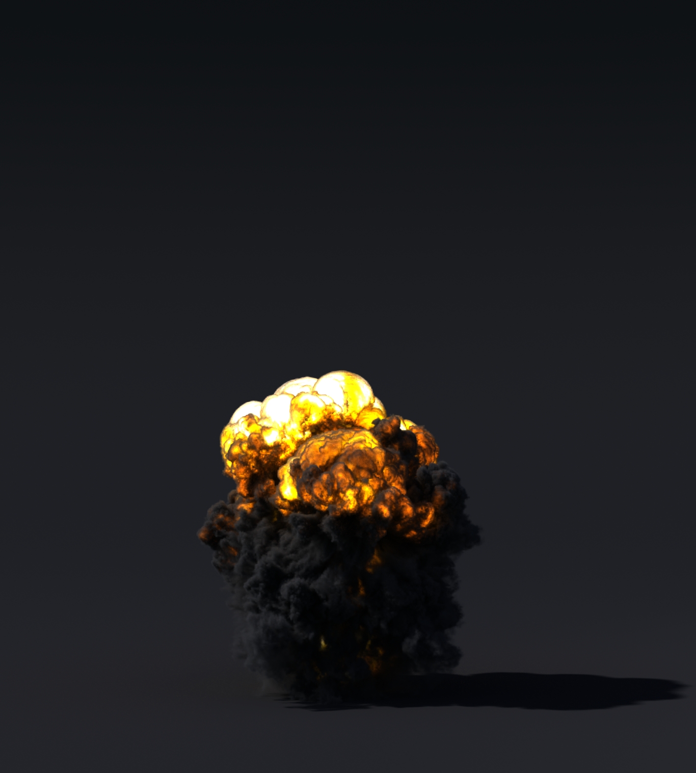
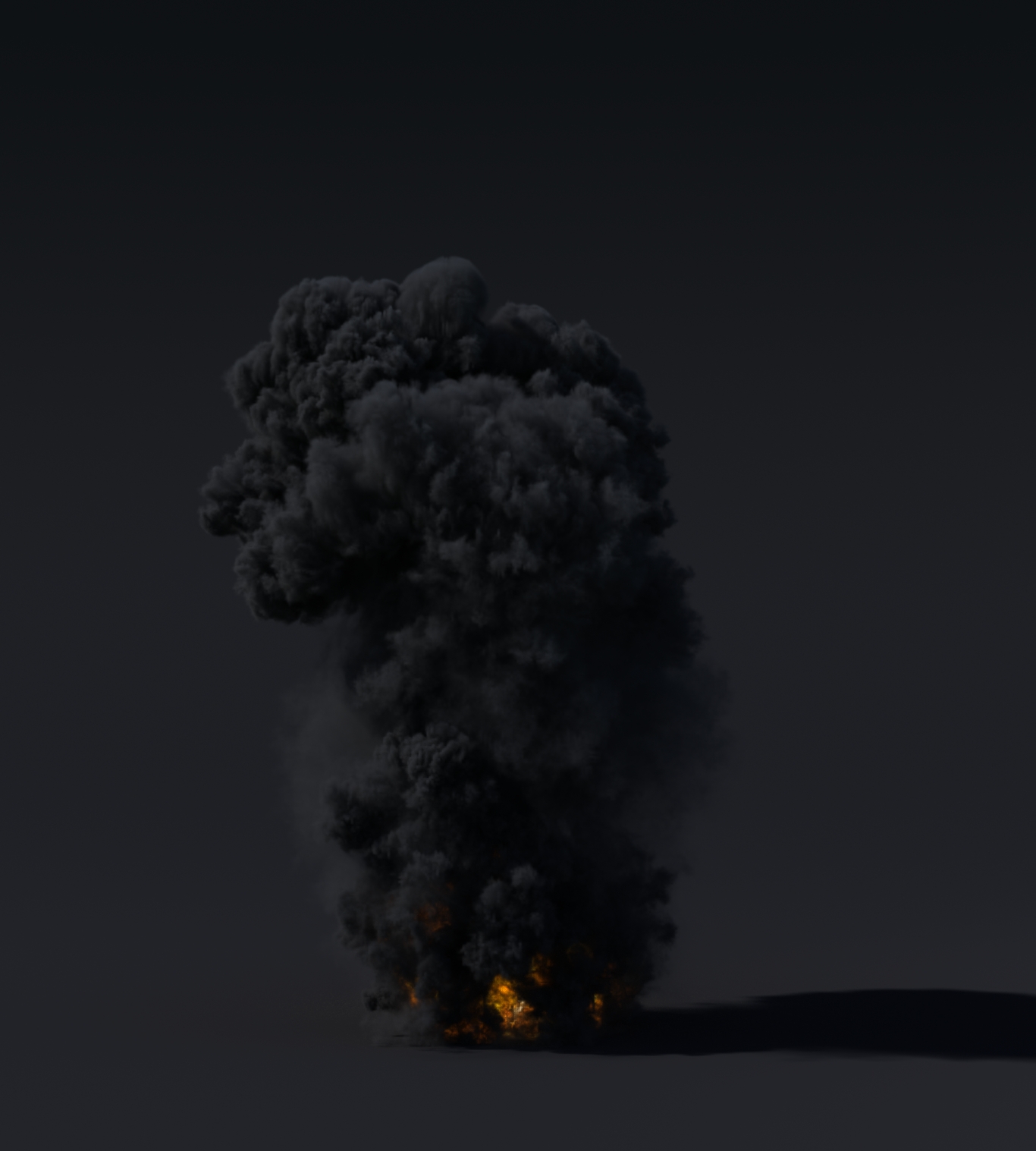
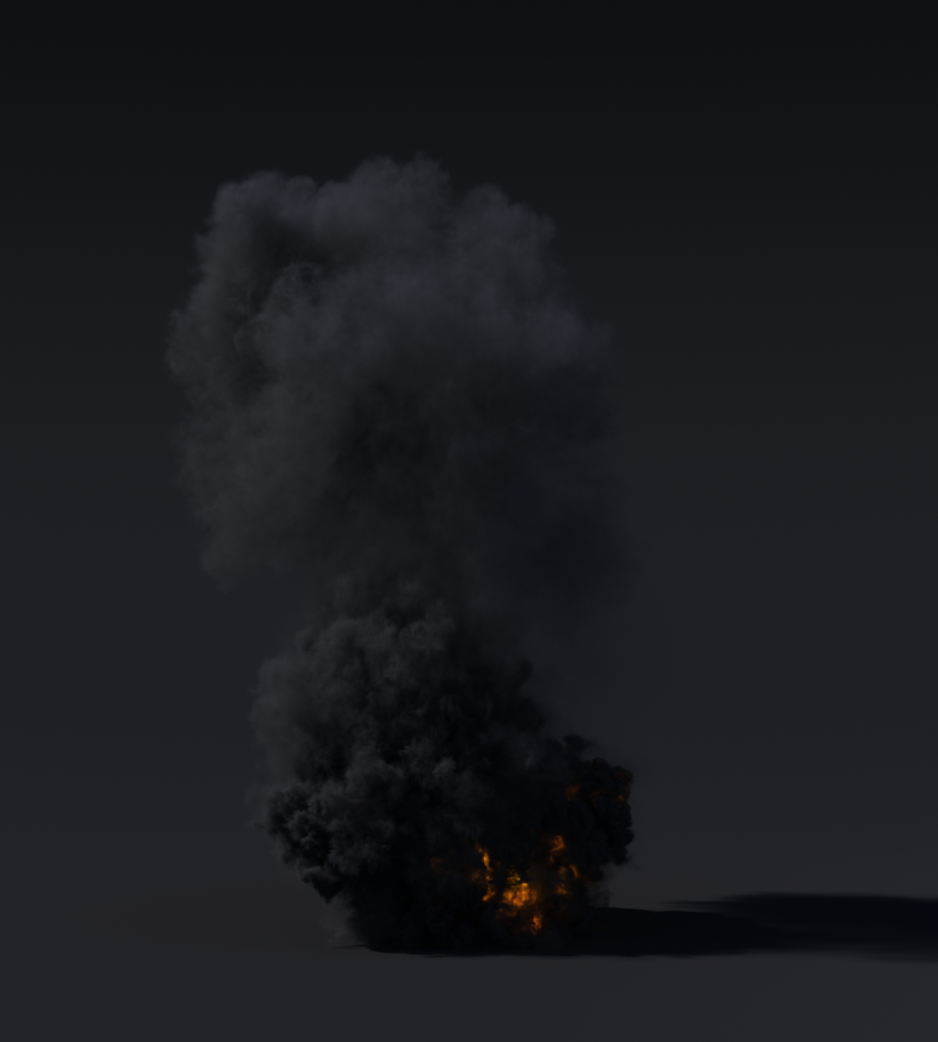
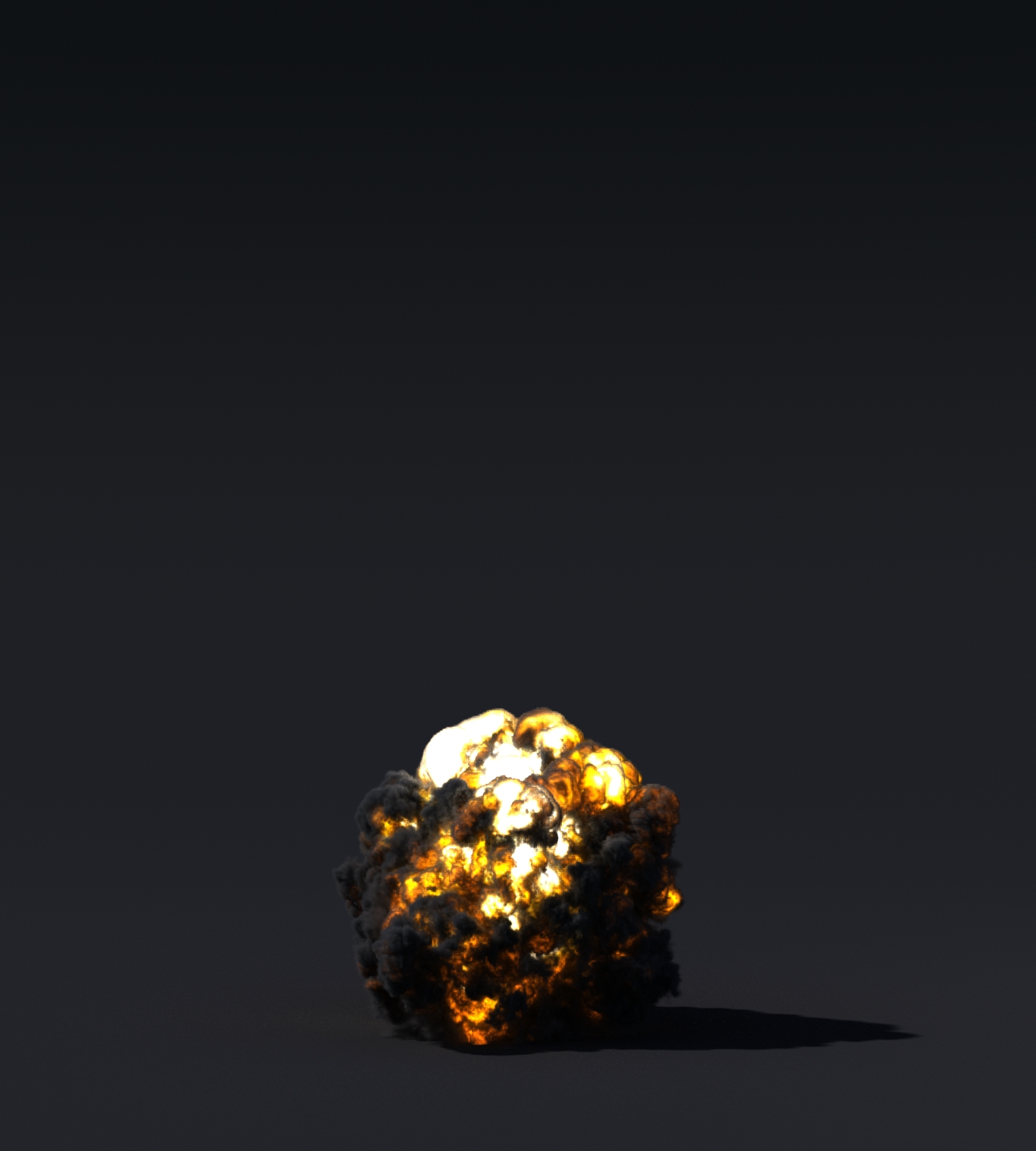
Houdini Take 4 - Explosion

Well, if you're going to try and learn Houdini, eventually you've got to simulate an explosion.

Here is my attempt at doing just that:

I rendered it with Mantra PBR and I really like the look of it but the render times are killing me. Some of the frames took around 7 hours to render! Now, I'm still new to Houdini so I've got a lot to learn when it comes to render settings. That being said, I'm sure there is a way to reduce the render time.

For the most part, this is a default Houdini explosion. I played with some of the turbulence and density settings on the explosion but mainly focused my time on the shading of the explosion.

Most of the changes were made on the ramp for the fuel and smoke.

Houdini Take 3 - Ocean Waves

After watching some fluid sims that were done in Houdini, I tried to give it a shot. 

Although this isn't a true water sim, because it's just a piece of displaced geometry, I was still impressed by how realistic it looked.

For this particular sim, I wanted to focus more on the lighting and rendering.
I played with the ramp for the ocean until I got something I liked. The only changes I made to the default sim settings was changing the wave height and the amount of foam on the surface.

This was rendered using Mantra's PBR shader. Render times were around 13-16 minutes a frame with 1 spotlight and 1 environment light acting as the HDRI environment.

Total render time was around 52 hours for 240 frames. Not too bad but it could be improved.

Once again, Houdini does not disappoint.

Now I've got to do a real sim!

Houdini Take 1 - Wet Sand

I recently started playing around in Houdini 14 and was amazed at the complexity of this program. After watching Side Effects demo for Houdini 14 I was blown away by how realistic their sand simulations were.

I decided to get my hands dirty and try to make some wet sand in Houdini. Here's the result of my efforts.

I love how easy Houdini makes it to change the parameters of the sim.


I had a lot of fun getting into Houdini and figuring out how everything works.

Vray Infinite Light Fix MEL Script

Created during the Dave School production "Aliens Minimates", I created a MEL script during the Lighting phase of production that would allow the user to bypass an error that occurs when you reference Vray lights into a scene.

Sometimes, when you reference a Vray light into a scene, the intensity value will appear as "INF" which causes problems when it comes time to render the scene.

To fix this issue, the script takes the intensity value of each light that is selected and it creates an attribute on a controller with the name of each light. It then assigns the intensity value to that attribute. After that, it makes the intensity value on the light non-keyable, and it links the attribute on the controller to the intensity value on the light.

Making the light intensity non-keyable is the key to fixing the "INF" problem.

What you are left with is a controller with attributes that allow you to control the intensity of each light that was selected prior to running the script. 

This script is free for anyone to use, so if you want it click on the MEL icon below and the download will begin.

1.60 KB

PLC MEL Script

Created during the Dave School production "Aliens Minimates", I created a MEL script during the Rigging phase of production that would allow my fellow classmates to select a prop or character and create a PLC and an offset Move controller just by running the script.

This script is most useful when a lot of prop rigging needs to be done. It greatly reduces the amount of time needed to do simple tasks like centering objects and making global scale attributes.


A summary of what the Script does:
     -Based on the bounding box data of the selected object, it centers the object in world space, freezes the transforms, and deletes the history on the object.

     -It then creates a controller labeled PLC with a global scale attribute, while locking and hiding the scale attributes.

     -Lastly, it creates a "Move" controller that allows for additional rotation and translation.

This script is free for anyone to use, so if you want it click on the MEL icon below and the download will begin.

5.65 KB

Aliens Minimates Exploding Alien Simulation

Created during the Dave School production "Aliens Minimates", I was assigned to create a simulation of an Alien exploding and it's blood coming out of the body.


This particular simulation was created with Realflow using two SPH emitters pointed at hemispheres to allow the blood to fly back in a realistic way.
Both emitters had their own randomness to them due to specific noise fields and kill volumes that allowed the blood to spread in unique ways.

The final simulation was brought into Maya and rendered with Vray.

Beauty Retouching with Mocha

Created during attendence at the Dave School, the assignment was to take footage and digitally "fix it up".

Items changed included:

     - Eyes and teeth were brightened

     - White hair was reduced with multiple different keyers

     - Skin tone was smoothed out

     - Blemishes were removed

     - Face was warped slightly using Open Splines in Nuke


This project was roto-ed and tracked in Mocha and the final composite was done in Nuke.